
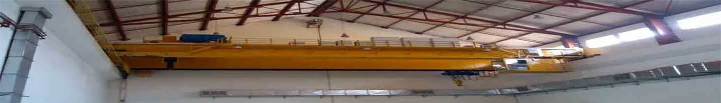

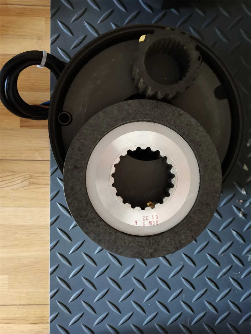
Brake Disk for AC Motor
$500.00 1 set
Qingdao Shanghai
L/C T/T
New
52314611
CE, ISO9001
WZX
General manufacturing
Type BFK458
Safety, fitting and operating instructions
The BFK458 series of spring applied brakes is available in two models, N or E.
N - fixed torque (non adjustable).
E - adjustable (with torque adjuster nut). . Nine sizes covering torques 2 to 600 Nm.
. Modular design options.
. Very robust.
. Simple, quick assembly.
Replaces the previous 14.448.series.
1. Introduction
1.1. Description
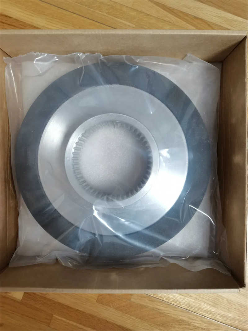
Braking torque is created by springs (2) pushing the armature plate (1) against the double-sided rotor (3) which in turn is pressed against a mounting surface. The splined hub (4) allows axial movement of the rotor across the airgap SLü . (See Fig. 2).
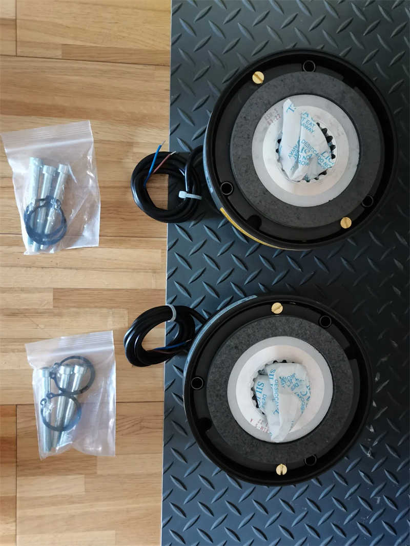
1.2. Identification
Brake stators are identified with a label as shown opposite.
Note that BFK458 is followed by size (06 to 25) and brake model:
Safety information
2.1. General notes
. These safety notes do not claim to be complete. In cases of questions or problems please contact Lenze.
. At the time of supply the spring operated brake is state-of-the-art and ensures basically safe operation.
The spring operated brake may be a source of danger for persons, the brake itself and other material assets of the operator if it is improperly modified or used by unqualified personnel.
. only operate the spring applied brake in a perfect condition.
Operator
An operator is any qualified person who uses the drive system or on behalf of whom the spring operated brake is used. The operator or his safety officer are obliged:
. to check whether all relevant regulations, notes, and laws are observed.
. to make sure that only qualified personnel work on and with the drive system.
. to ensure that the personnel have the operating instructions available for all corresponding operations.
. to prohibit non-qualified personnel from working with and on the spring-operated brake.
Qualified personnel
Qualified personnel are persons who - because of their education, experience, instructions, and knowledge about the corresponding standards and regulations, rules for the prevention of accidents, and operating conditions - are authorized by the persons responsible for the safety of the plant to perform the required actions and who are able to recognise the potential hazards.
2.2. Environmental restrictions
. No explosive or aggressive atmosphere.
. Normal ambient temperature -20º to +40ºC. Outside this range, refer to Lenze Ltd.
. With high humidty and low temperature, care must be taken to protect armature plate and rotor from freezing.
. Electrical connections must be protected.
. Cooling airflow must not be impeded.
| Size | 06 | 08 | 10 | 12 | 14 | 16 | 18 | 20 | 25 | |
| Rotor diameter, mm | 60 | 77 | 95 | 115 | 124 | 149 | 174 | 206 | 254 | |
| Rotor thickness (new), mm | 6.0 | 7.0 | 9.0 | 10.0 | 10.0 | 11.5 | 13.0 | 16.0 | 20.0 | |
| Minimum rotor thickness, mm | 4.5 | 5.5 | 7.5 | 8.0 | 7.5 | 8.0 | 10.0 | 12.0 | 15.5 | |
| Rated airgap, SLü, mm | 0.2 | 0.3 | 0.4 | 0.5 | ||||||
| OPERATING Max torque, Nm BRAKE Max airgap, mm | 4 | 8 | 16 | 32 | 60 | 80 | 150 | 260 | 400 | |
| 0.5 | 0.75 | 1.0 | 1.25 | |||||||
| HOLDING BRAKE | Max torque, Nm Max airgap, mm | 6 | 12 | 23 | 46 | 95 | 125 | 235 | 400 | 600 |
| 0.3 | 0.45 | 0.6 | 0.75 | |||||||
| Hand release clearance S+0.1 | 1.0 | 1.5 | 2.0 | 2.5 | ||||||
| Hand rel. adj. setting S + SLü | 1.2 | 1.8 | 2.4 | 3.0 | ||||||
| Torque reduction per detent position (Type E only) Nm | 0.2 | 0.35 | 0.8 | 1.3 1.7 1.6 | 3.6 5.6 | 6.2 | ||||
| Adjuster nut projection | 4.5 4.5 7.5 | 9.5 | 11.0 10.0 | 15.0 17.0 | 19.5 | |||||
| h1 max | mm | |||||||||
3.2. Coil values
| Size | 06 08 10 12 14 16 18 20 25 | ||||||||
| Coil power (20ºC), W | 20 25 32 40 53 55 85 100 110 | ||||||||
| Nominal coil 24V Resistance, Ω) (at 20ºC) 103V 180V Values may vary ±8% 205V | 20 531 1620 2101 | 23 424 1296 1681 | 19.2 332 1013 1273 | 14.4 265 810 1051 | 11.5 200 611 793 | 10.5 190 589 751 | 6.8 125 387 494 | 5.8 106 324 420 | 5.2 97 295 382 |
3.3. Switching times
3.4. Operating frequency/friction work
The permissible operating frequency depends on the friction work. With high speed and friction work, the wear increases strongly, because very high temperatures occur at the friction faces for a short time.
Values for operating frequencies dependent on friction work per operation are given in INTORQ publication 405520 GB.
3.5. Mounting requirements
- The shaft should be toleranced to k6. Provide axial location for securing the hub.
- Provide a key in the shaft equal to the length of the hub. For up to standard torques, a rounded key may be used, above these values a square-ended key across the full width of the hub is preferred on brakes size 16 and above.
The mounting surface should be square to the shaft with 5-8 µm or fine turned finish over the rubbing area, made of steel or cast iron. If a flat ferrous surface is not available use the friction plate or mounting flange.
Recommended shaft tolerances. Dimensions µm
| Shaft tolerance Over Up to | Tolerance | Lower limit | Upper limit | |
| 6 10 18 | 10 18 30 | k6 | +1 +1 +2 | +10 +12 +15 |
| 30 50 | m6 | +2 | +18 | |
3.6 Emission
Electromagnetic compatibility
For normal circuits with unsmoothed d.c. voltage via bridge connection, the spring applied brake series BFK458 complies with EN50081 Part 1.
The entire circuit only complies when it is configured according to one of the eight options listed in the table below.
| Circuit: | Options | With a rectifier that: complies does not with comply with standard standard | Spark suppressor in parallel to AC voltage | Mains filters | ||
| DC switching | < = 5 Switching operations/minute | 1 | * | |||
| 2 | * | * | ||||
| > 5 Switching operations/minute | 3 | * | * | |||
| 4 | * | * | ||||
| AC switching | < = 5 Switching operations/minute | 5 | * | |||
| 6 | * | * | ||||
| > 5 Switching operations/minute | 7 | * | ||||
| 8 | * | * | ||||
4. Installation
4.1 Tools required 4.2 Fixing screw dimensions
| Size | 06 08 10 12 14 16 18 20 25 | ||||
| For direct mounting or with friction plate | M4x40 M5x45 M6x55 M6x60 M8x70 M8x80 M8x90 M10x100 M10x110 | ||||
| For use with mounting flange | M4x35 M5x40 M6x50 M6x55 M8x65 M8x70 M8x80 M10x90 M10x100 | ||||
| Minimum clearance required behind flange, mm | 0.5 1.0 2.0 3.0 1.5 0.5 0.8 2.1 5.0 | ||||
| For mounting through flange | M4x45 M5x50 M6x65 M6x70 M8x80 M8x90 M8x100 M10x110 M10x120 | ||||
| Flange fixing screws DIN 6912 | 3xM4 3xM5 3xM6 3xM6 3xM8 3xM8 4xM8 4xM10 6xM10 | ||||
| Assembly bolts tightening torque, Nm | 2.8 | 5.5 | 9.5 | 23.0 | 46.0 |
4.3 Assembly of mounting flange
Check there is the minimum clearance behind the flange as given in Section 4.2. Without this clearance the minimum rotor thickness cannot be reached. It is not allowed for screws to "bottom"onto the mounting surface.
NOTE! For sizes 18 and 20 brakes only 4 mounting holes are present, in order to provide clearance for the hand release bolts. Align the mounting flange accordingly before assembling the brake.
4.4 Assembly of friction plate
Check the clearance holes align with the threads in the mounting surface.
NOTE! The lip edge must be away from the mounting surface.
4.5 Assembly of hand release (if fitted)
Note that the cranked yoke 14.1 (Fig. 7) can be assembled either with the crank pointing towards the mounting surface or away from it.
1. Insert the compression springs (14.2) into the bore holes of the armature plate.
2. Push the bolts (14.4) through the washers (14.3).
3. Push the screws and washers (14.4 and 14.3) through the compression springs (14.2), armature plate (1) and stator (7).
4. Locate the trunnions (14.5) in the yoke (14.1).
5. Screw the hexagon screws (14.4) into the trunnions (14.5) in the yoke (14.1) 4.6 Assembly of brake
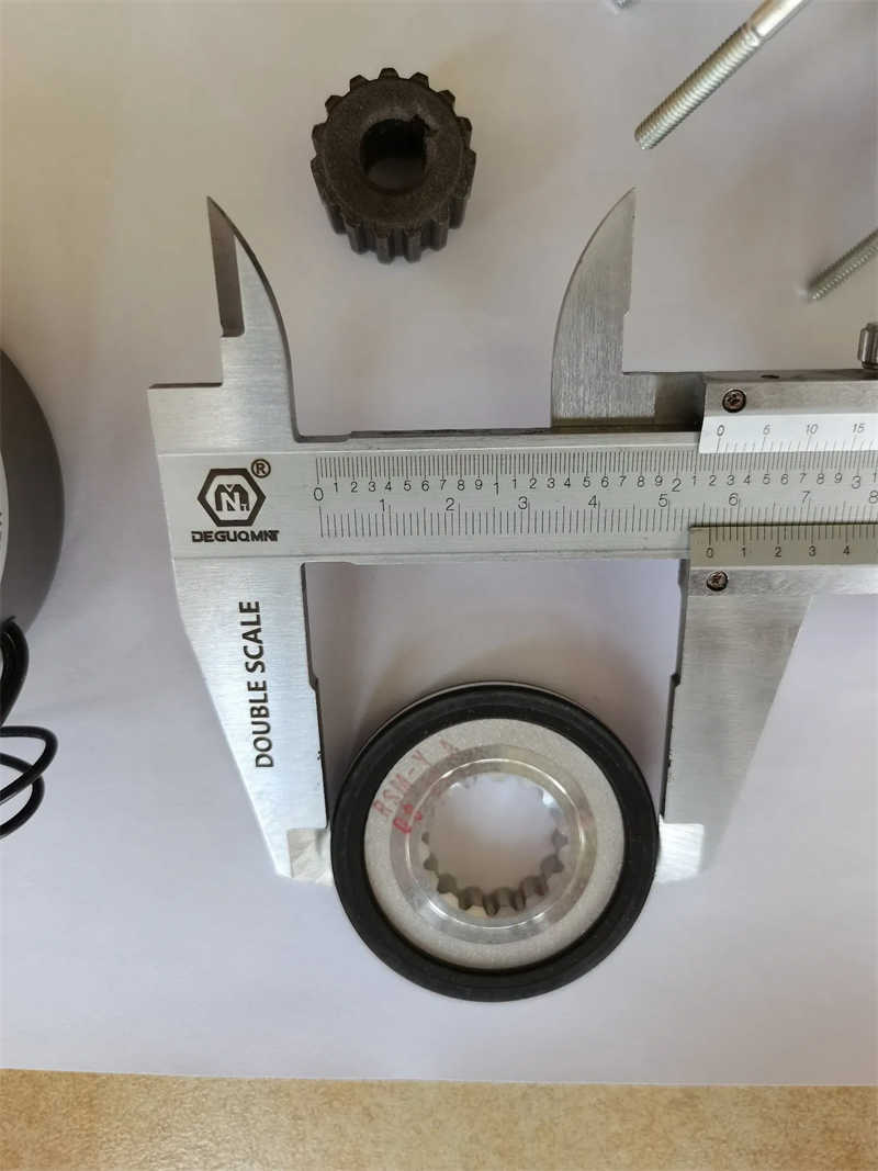
1. HUB
Fit the hub to the shaft using a key. The hub should be a transition fit.
DO NOT hammer the hub onto the shaft! Secure it axially, i.e. with a circlip
2. ROTOR
Mount the rotor onto the hub and check it will slide axially.
(For reversing applications, it is recommended to additionally secure the hub with a suitable adhesive.)
3. STATOR-ARMATURE
Mount the stator armature onto the wall surface using the assembly bolts. Tighten the bolts to the rated torque (Section 4.2), then remove the plastic transit clips.
4. AIR GAP
The airgap is preset at manufacture but should be checked on assembly. Check the airgap (SLü rated) using a feeler gauge (Section 3.1). If adjustment is required, refer to maintenance (Section 6.3).
5. VOLTAGE
The brake is now ready for operation. Check that the voltage supplied to the coil is within - 10% to +5% of the rated DC voltage.
4.7 Assembly of cover seal
Pull the cable through the seal. Assemble over the stator pressing the lips of the seal into the groove of the stator and flange, or over the lip of the friction plate. 4.8 Electrical Connections
24V coils
INTORQ spring applied brakes operate best with an unsmoothed d.c. supply.Where a 24V coil is fitted, the Lenze Simplavolt power supply units can be used.
103V, 180V, 205V coils
A rectifier should be selected to match the coil
voltage to the supply voltage, based on:
ull wave rectified Supply voltage (a.c.)
coil voltage (d.c.) = 1.1
Engagement time
When switching a brake on the a.c. side of the supply engagement times are extended by 3-6 times those shown under paragraph 3.4. The simplest form of connection to a motor in parallel with the rectifier and brake coil further extends the engagement time. This is because the motor which is already switched off but still running, continues to excite the brake. With falling loads such as hoists, lifts and cranes, it is ESSENTIAL to switch the brake coil on the d.c. side of the supply. A spark suppressor is required to prevent inductive voltages from damaging the brake coil or rectifier. Reducing the brake torque also prolongs brake engagement times.
Disengagement time
The disengagement time is not influenced by a.c. or d.c. switching. It can only be shortened by over-excitation of the coil, for example by using a force voltage rectifier.
Commissioning and Operation
For brake motors disconnect the links from the motor terminals when checking the release function of the brake. The motor must be free from residual torque and must not rotate. If the rectifier is connected to the star point of the motor, the earth must also be connected to this point.
. Check the brake regularly for: unusual noise - excessive temperatures - loose assembly bolts - damage to cables
6. Maintenance
6.1 Inspection intervals
To maintain safety and efficient brake action, regular inspections are essential. The wear on the friction lining on the rotor depends on the operating conditions. High energy braking and frequent operation reduce the time until re-adjustment becomes necessary. The inspection intervals must be adapted to the operating conditions and can be prolonged if the wear is small.
6.2 Inspection
1. For brake motors, remove motor fan cowl and seal (if fitted).
2. Measure rotor thickness. Replace if below minimum permitted value (see Rated Data Section 3.1).
3. Check the airgap SLü between armature plate and stator using a feeler gauge and compare with maximum allowed depending on torque (Section 3.1). 6.3 Re-adjustment
If adjustment is necessary, proceed as follows:
1. Loosen assembly bolts (10) (See Fig. 12). 2. Turn the airgap adjustment tubes (9) into or out of the stator to reduce or increase the airgap (Note - 1/6 turn corresponds to approx 0.15mm). 3. Re-tighten the bolts to torque Fig. 13 (see Section 4.2). 4. Check the airgap. If necessary repeat the adjustment. Note: If fitted, the clearance S for the hand release is set on assembly and should not require re-adjustment.
| Brake size | 06 | 08 | 10 | 12 | 14 | 16 | 18 | 20 | 25 |
| Airgap setting SLü | 0.2 | 0.3 | 0.4 | 0.5 | |||||
| Assembly bolts tightening torque, Nm | 2.8 | 5.5 | 9.5 | 23.0 | 46.0 | ||||

Contact Supplier
Our Top Selling Products


LINKS : Dongqi Crane